Overview
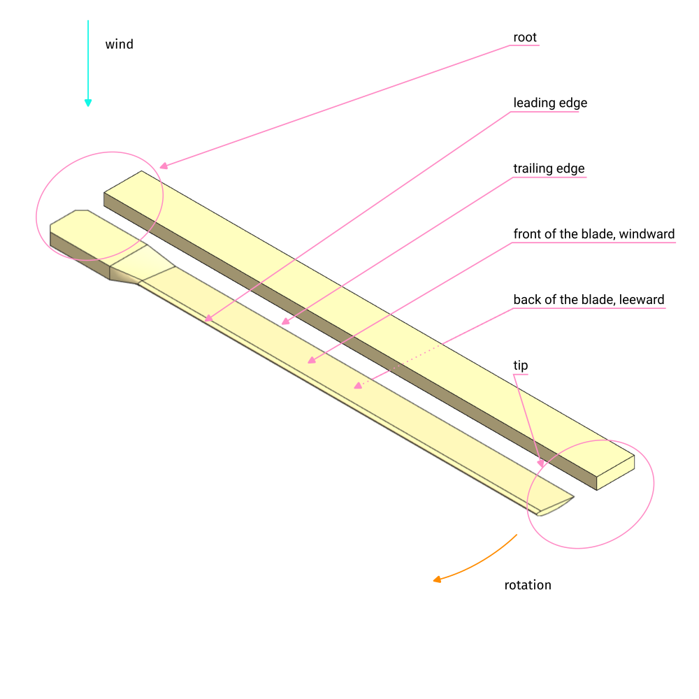
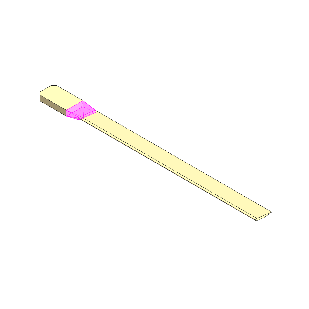
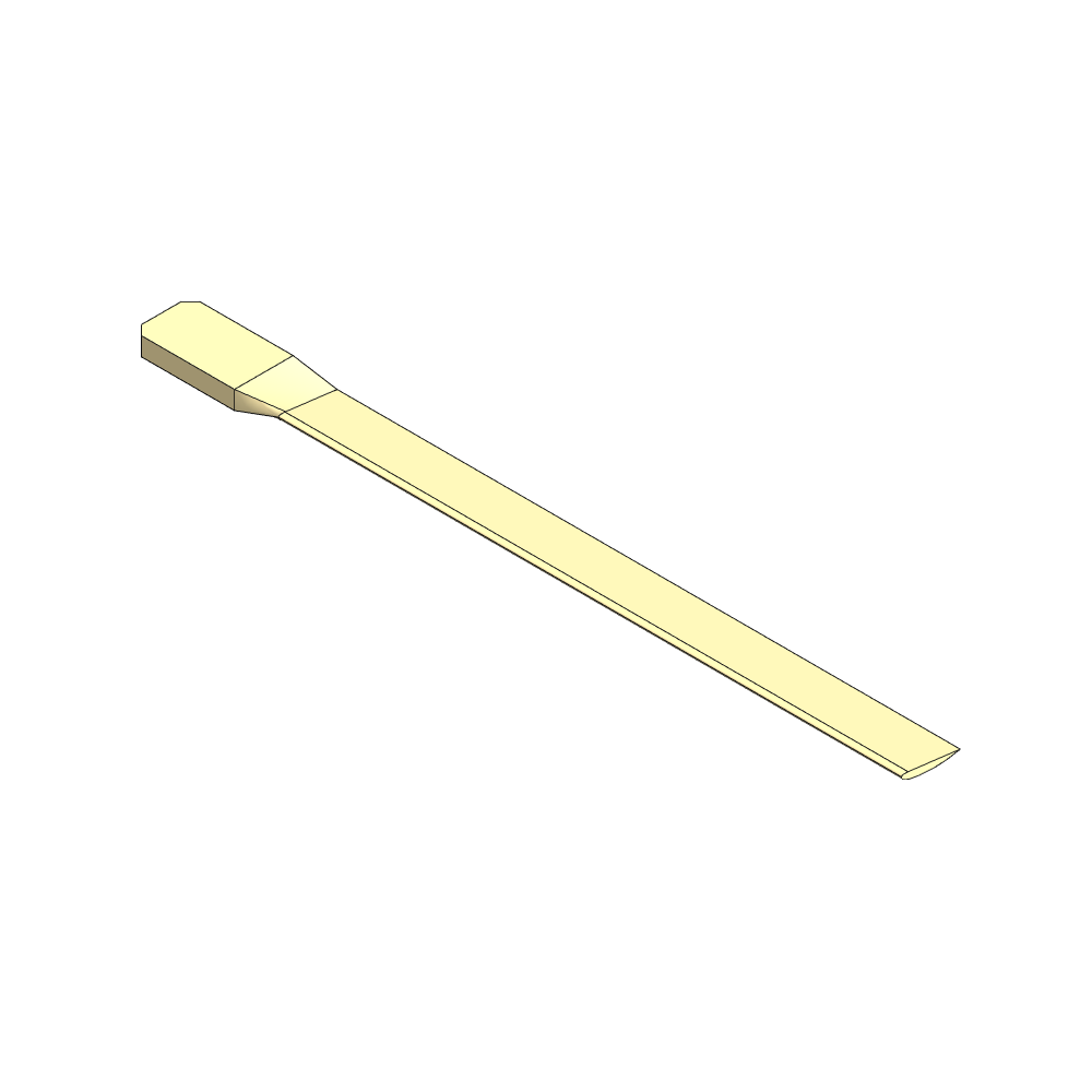
In this section we focus on carving the Rotor Blade by hand from a piece of wood. Use the CAD file to gain a better understanding of the diamensions as long as we didn't put numbers on the renderings.
This method is heavily inspired by Performance analysis and improvement of a small locally produced wind turbine for developing countries, section "Blade manufacturing manual for the new rotor design", p.111, by Nienke Hosman.
Following variables are used:
| Variables | mm |
|---|---|
| blade length R | 900 |
| wood length L | 1000 |
| blade width W | 80 |
| minimum wood thickness H | 25 |
| chord C | 80 |
| M | 200 |
| N | 140 |
| B | 67 |
| A | 33 |
| D | 10 |
| E | 13 |
| airfoil thickness T | 10 |
| a1 | 10 |
| a2 | 3 |
| a3 | 24 |
| blade angle θ | 7° |
Materials
See pos. 1 in the BOM, not all materials listed there may be required at this point.
Build
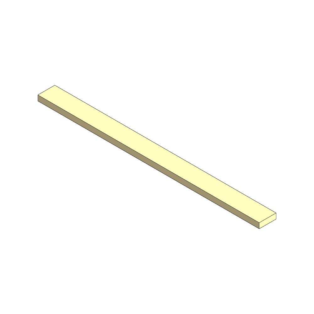
1. Define up- and downwind side of the blade
 View: Perspective
 View: Looking from blade tip to root
2. Carving the windward face
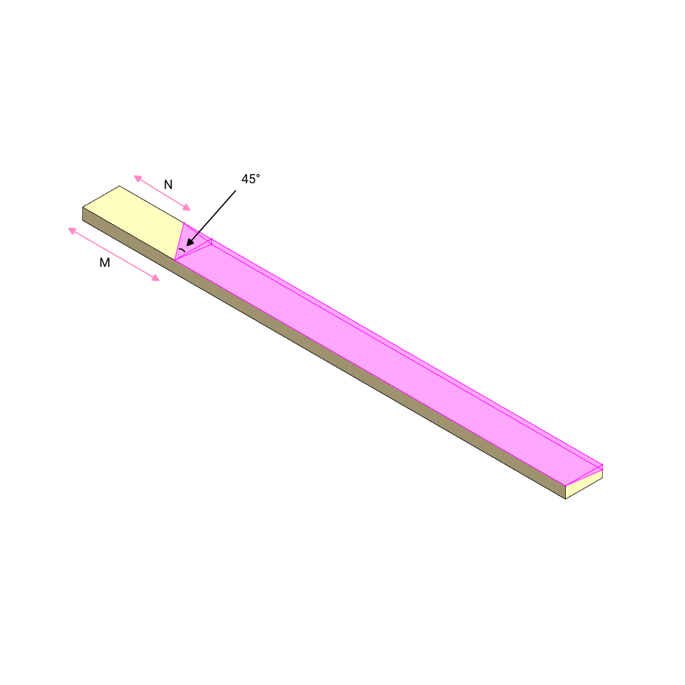 View: Perspective
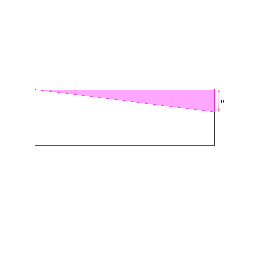 View: Looking from blade tip to root
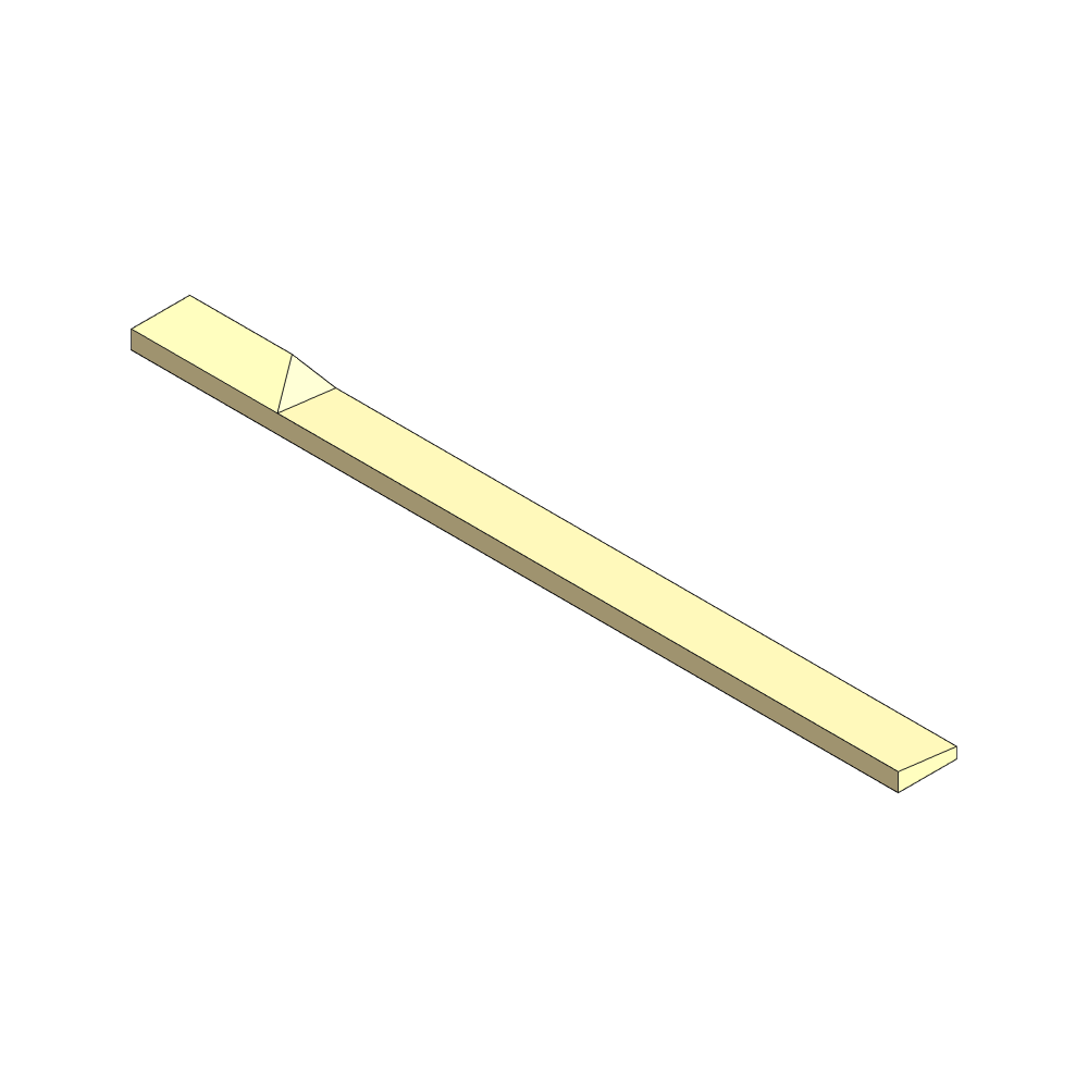 View: Perspective
3. Carving the downwind side and blade thickness
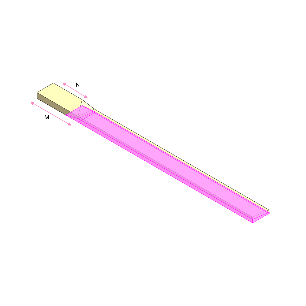 View: Perspective
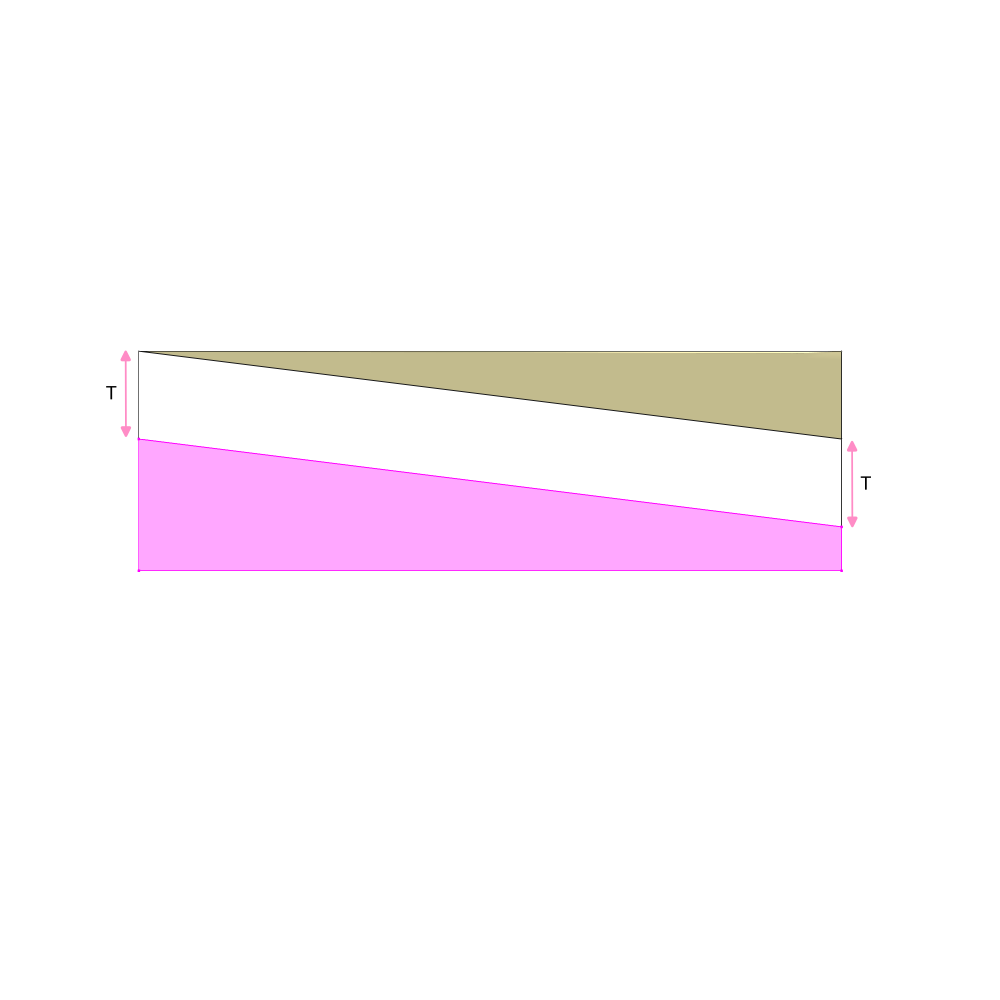 View: Looking from blade tip to root
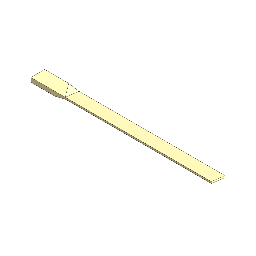 View: Perspective upwind side
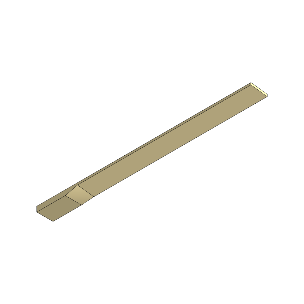 View: Perspective downwind side
4. Carving the airfoil shape
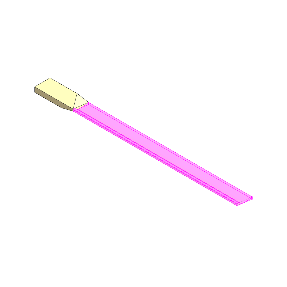 View: Perspective upwind side
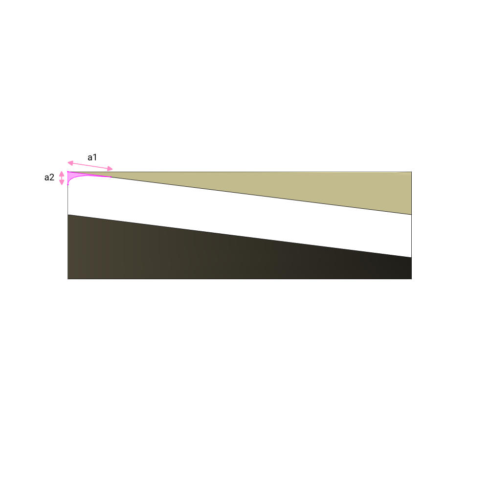 View: Looking from blade tip to root
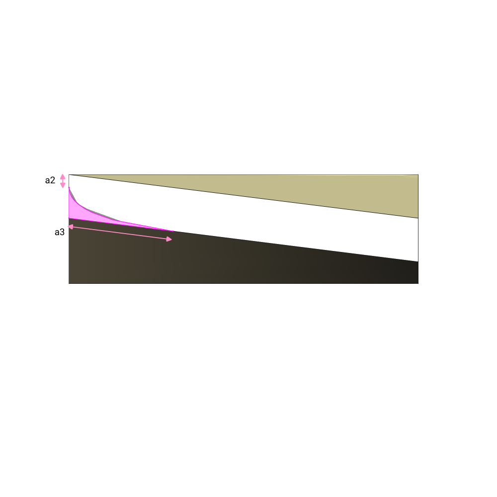 View: Looking from blade tip to root
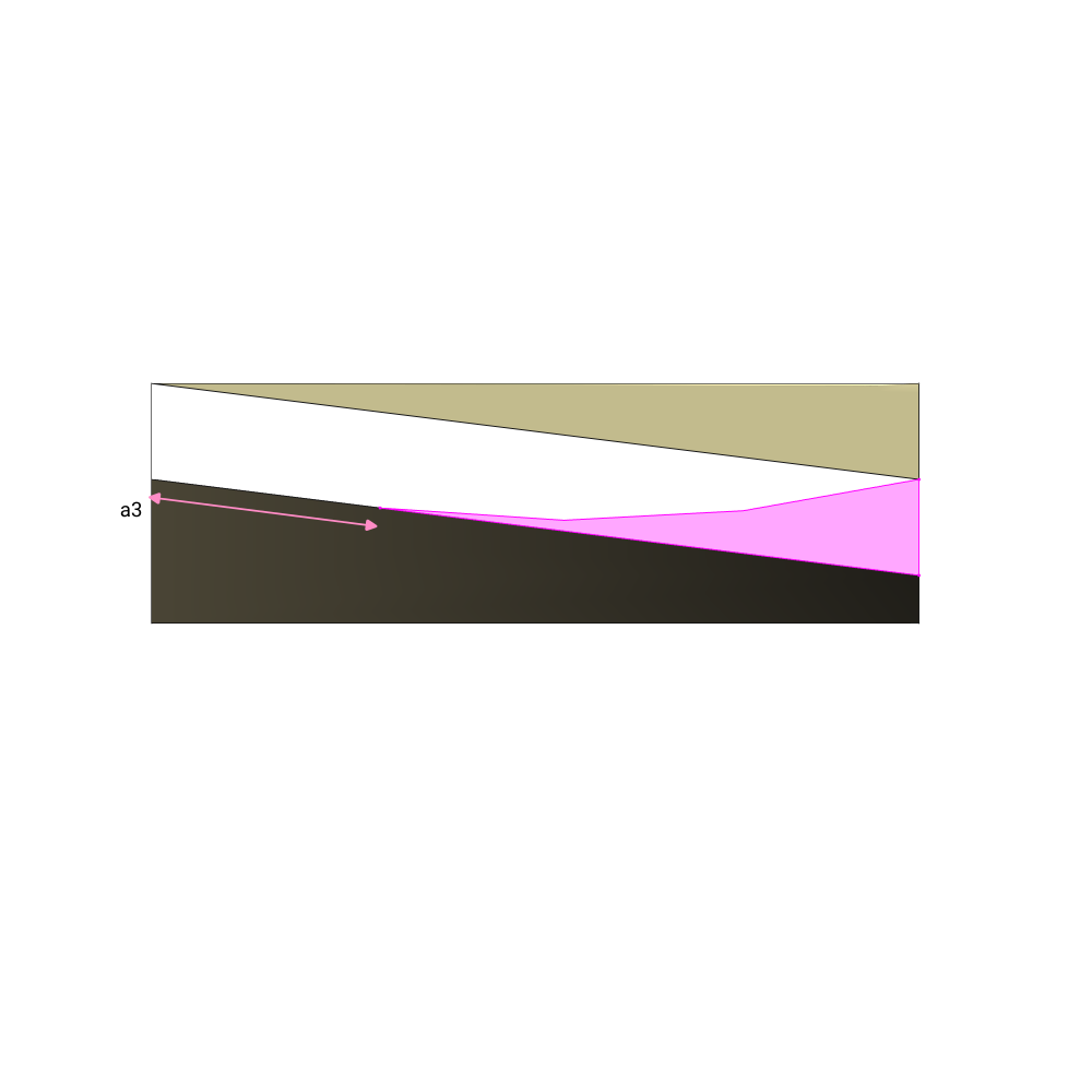 View: Looking from blade tip to root
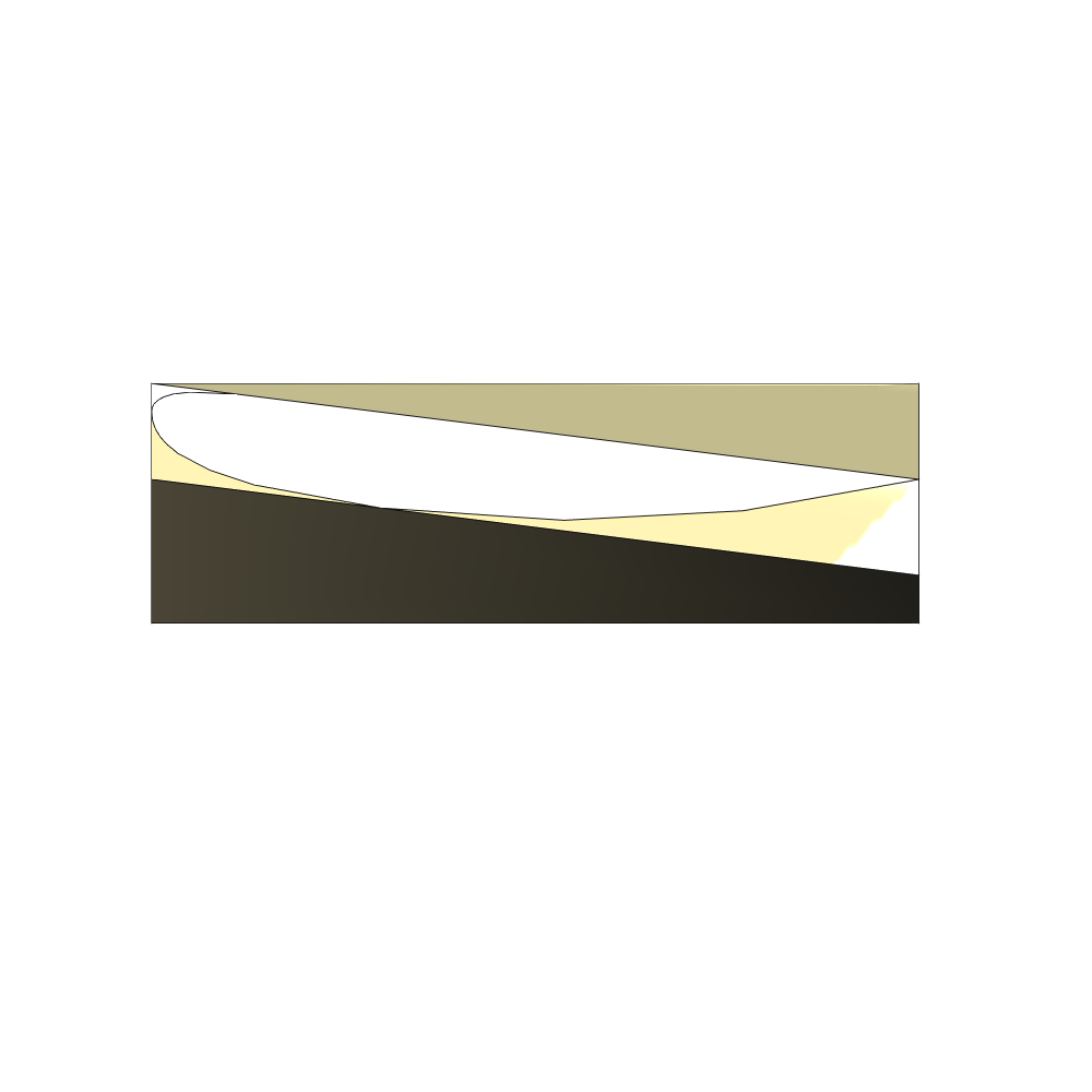 View: Looking from blade tip to root
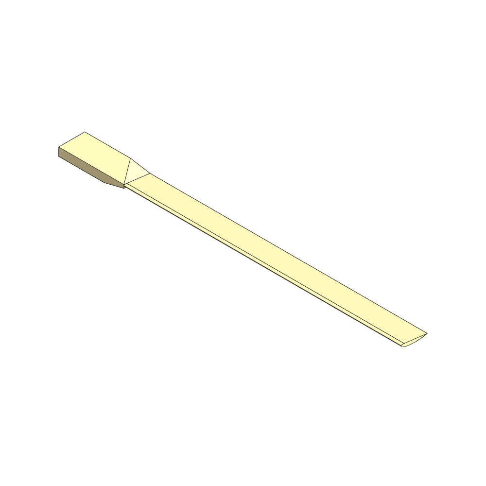 View: Perspective upwind side
5. Cut the edges of the root
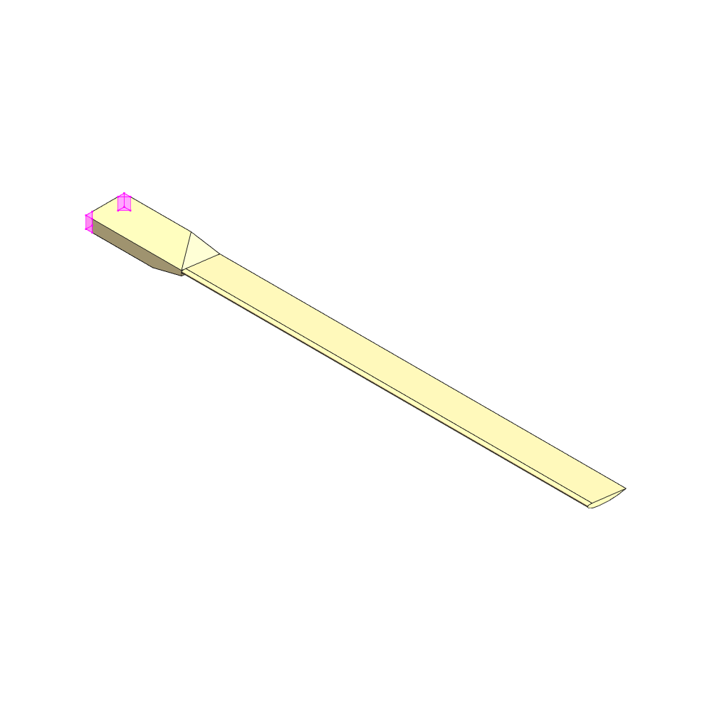 View: Perspective upwind side
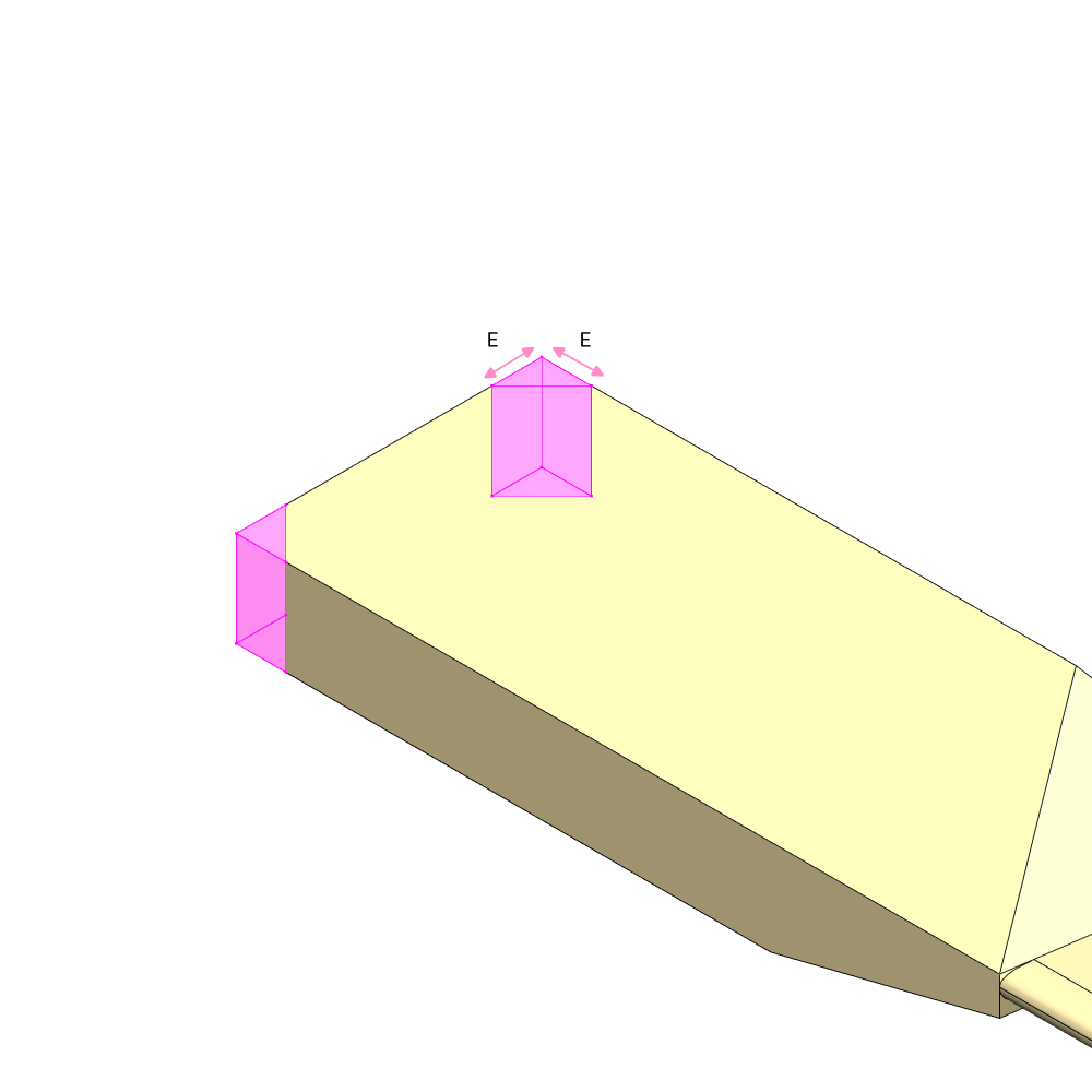 View: Perspective blade root
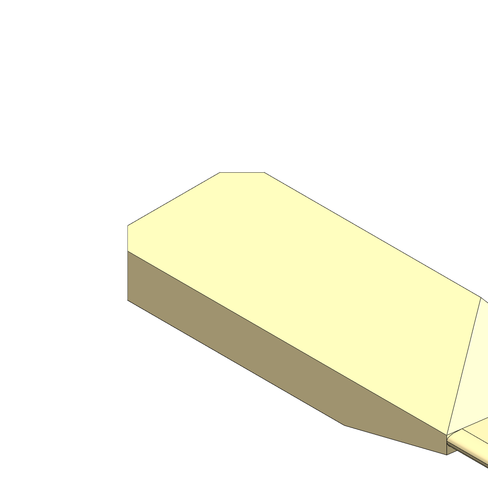 View: Perspective blade root
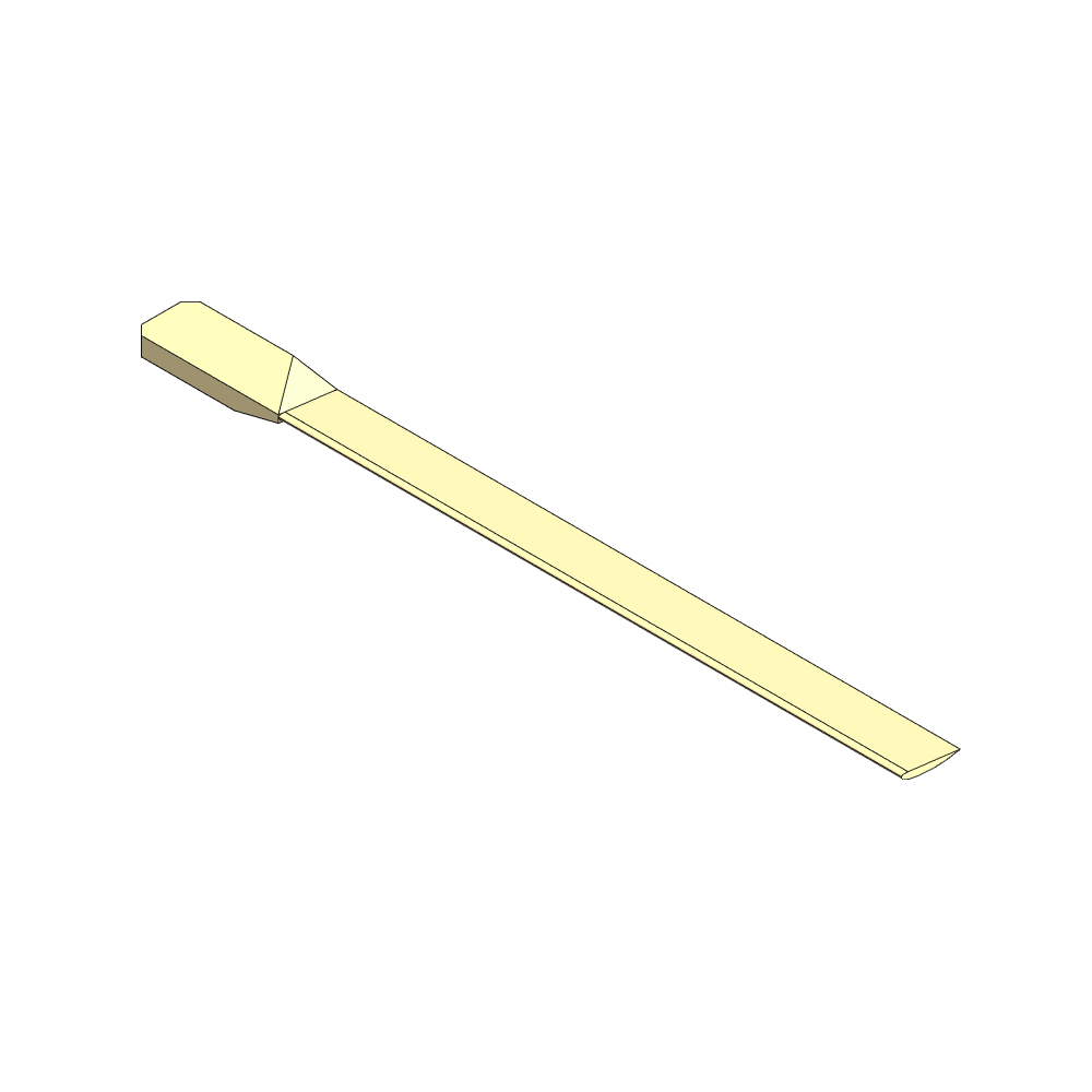 View: Perspective upwind side
